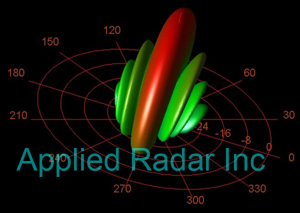
The antenna is undoubtedly one of the most important elements in a modern radar, comms or EW system as it defines the system’s beam size and shape, gain, and sidelobes (or clutter rejection). Any nulls or variations in gain can have a negative impact on system performance. Simple antennas such as dish antennas used for satellite or point-to-point comm links, Omni-directional comm antennas such as vehicular, GPS or cell phone, or airborne comms antennas have fixed patterns. Many modern advanced systems including radar systems and 5G communcations systems are required to scan a narrow beam. Electronic warfare systems are generally required to perform direction finding (or DF), which requires scanning a beam. The scan rate and method of scanning becomes an important issue. Many modern systems employ phased-array antennas in order to perform this beam scanning efficiently. There are many ways to perform this electronic scanning, including MMIC phase shifters and digital beamformers. Applied Radar, Inc. has intimately involved in digital beamforming for nearly 20 years. Antenna system cost is also a key issue, and in all but the most expensive system, system trades in the antenna area need to be performed in order to reduce system cost. Applied Radar is experienced with the development of advanced antennas for numerous applications including automotive radar, high-data-rate airborne communications, shipboard radar systems, comm-on-the-move, airborne intelligence, surveillance, and reconnaissance (ISR), and ground-based sensors and systems.